Poly Bevel
Visit the Node Bible
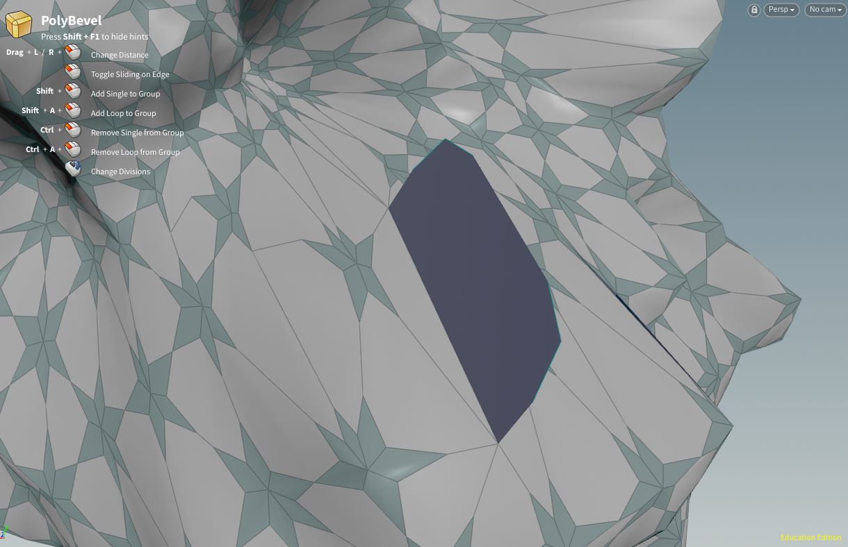
Poly Bevel
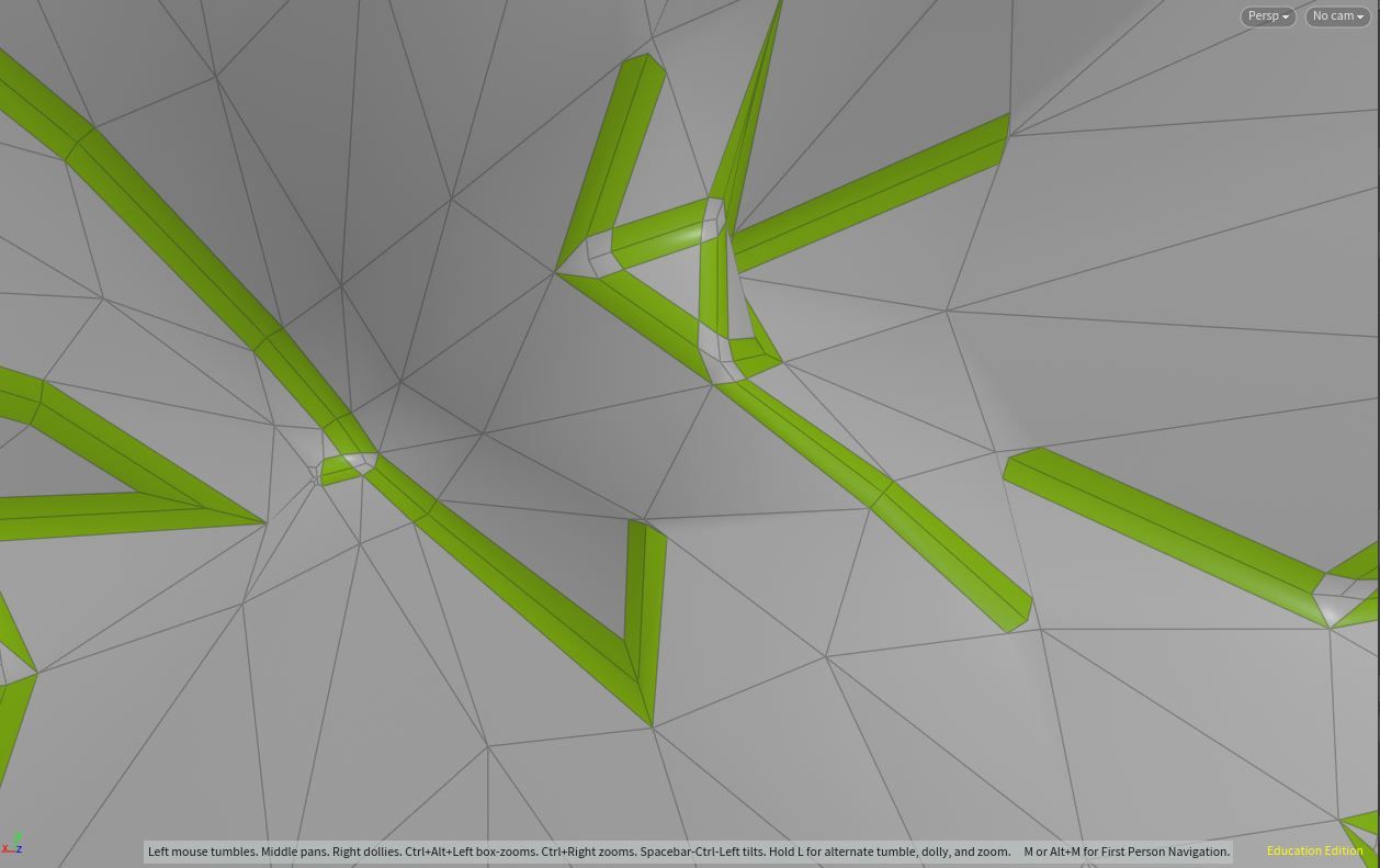
Unfortunately, the poly-bevel node has a lot to be desired (as of writing Jan. 9th 2023). When using this node, you will find many parameters that are either broken or that create bad geometry. So, if you are having issues with this node, then it is wise to follow it with a clean SOP, fuse, or poly doctor node to ensure that your topology has not been corrupted.
In practice, it's best to tread carefully when using this node, and make sure that you inspect each bevel before moving on.
General Parameters:
Group + Group Type:
Exclusions:
(If mode is set to Primitives, you will see these options...)
Ignore Polygon Bridge Edges
(If mode is set to Points, you will see these options...)
Ignore Flat Points (Coplanar Incident Polygon)
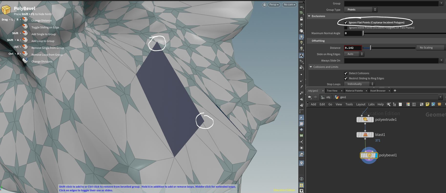
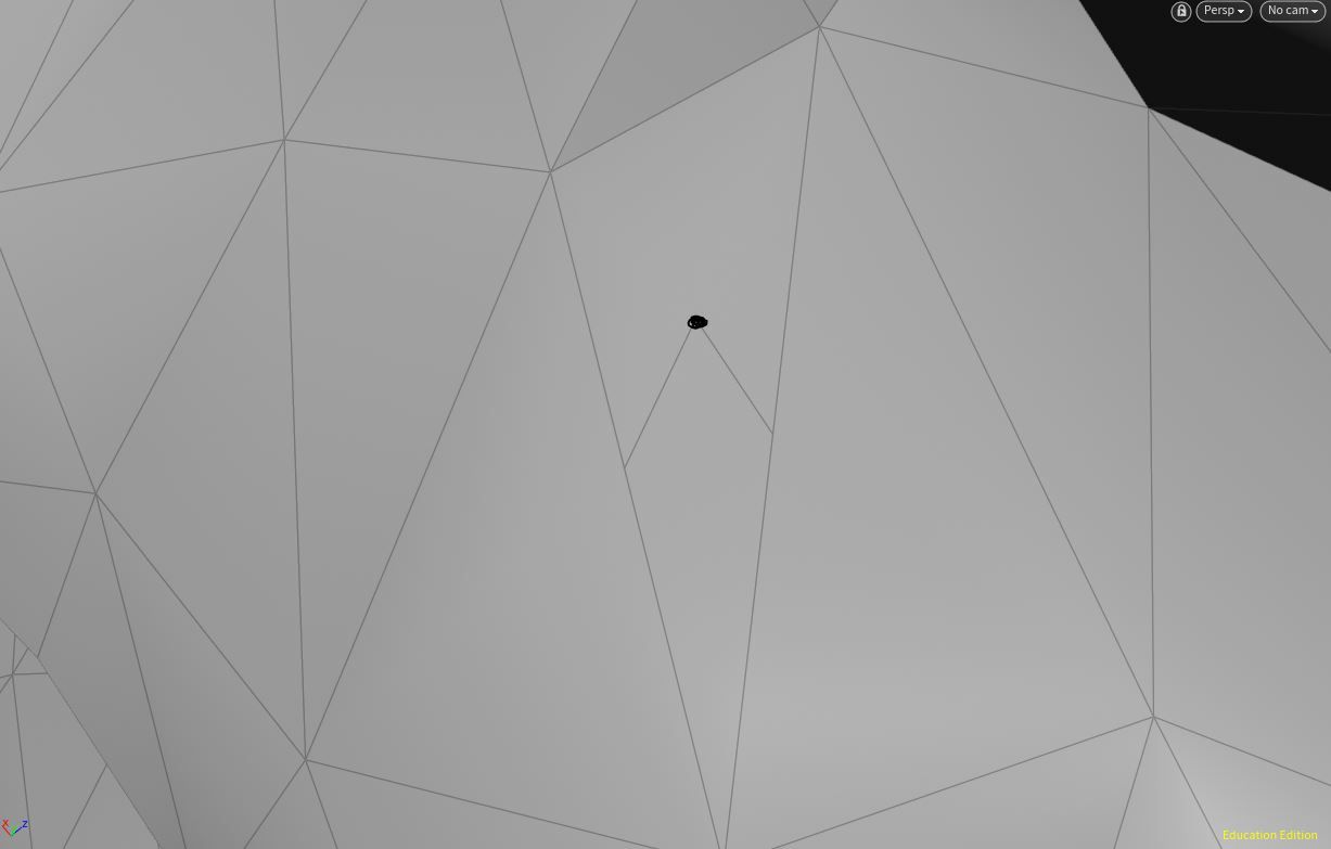
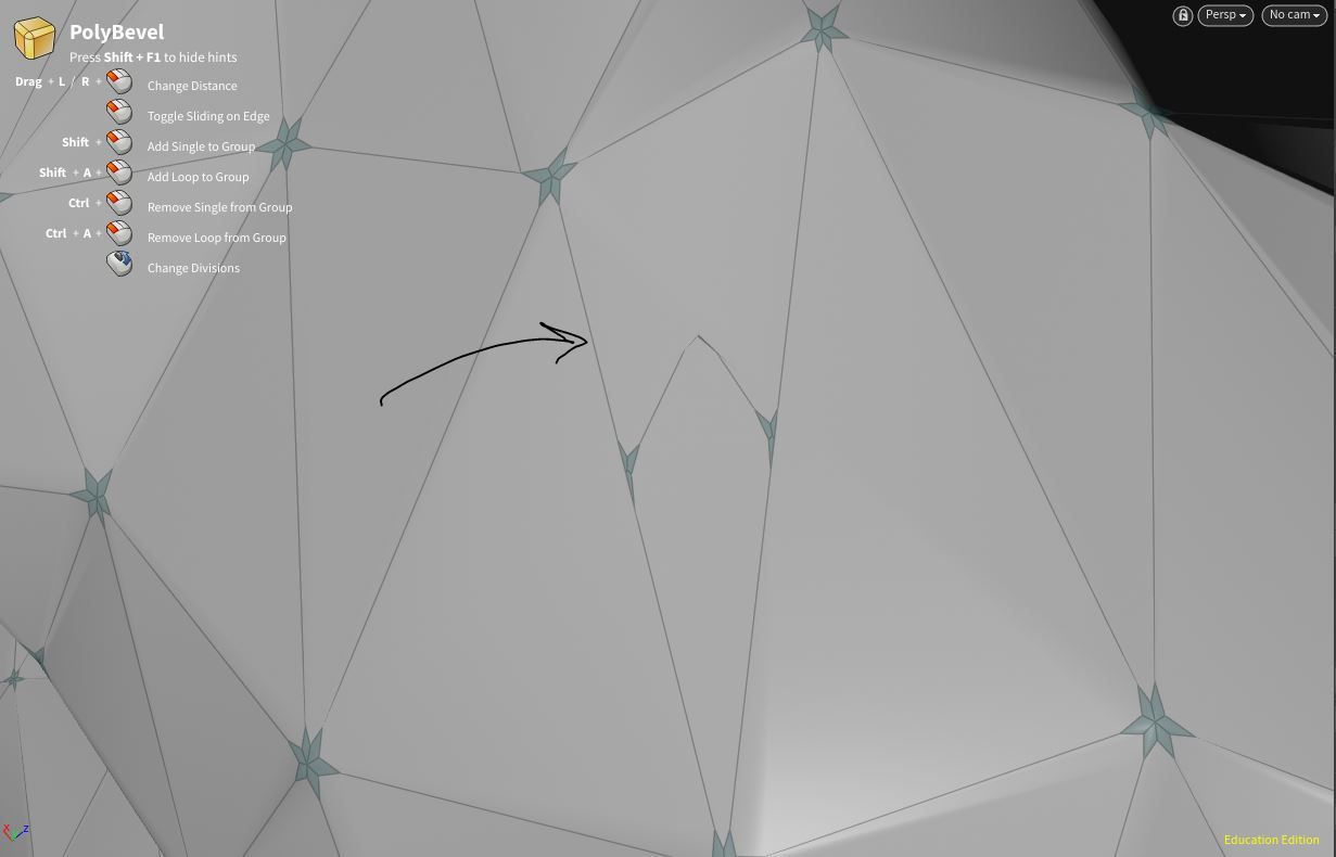
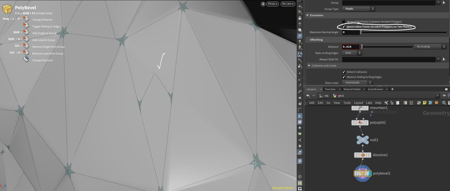
Ignore Inline Points (Incident Polygons on Two Planes):
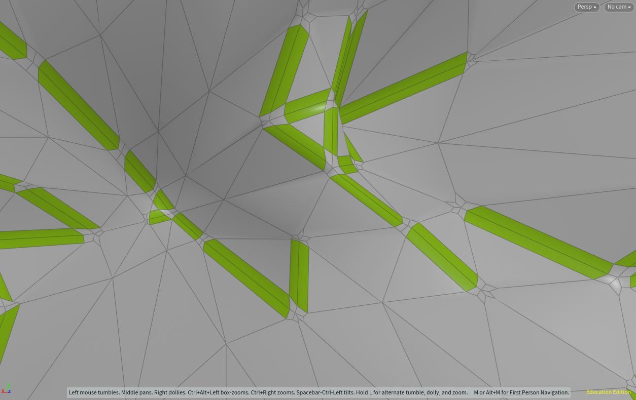
-- To see this in action, look at a point that’s located in the middle of a flat polygon like this:
Offsetting:
Distance:
-- This is how far out a bevel should go
Slide on Ring Edges:
-- These parameters will control how the edges slide across your mesh as they bevel. These settings are a bit confusing in how the document presents the information. In practice, it is best to switch between the different modes and settings to see if it gives you a better looking bevel. I’ve found that when bevels start to look ugly, it may help to set the mode to “Auto” and the Asymmetry Tolerance to a low value. In addition, it’s best to ignore what the documentation is saying, and see for yourself what the “Auto,” “Always,” and “Dont slide along any ring edges” do to the mesh.
Asymmetry Tolerance:
-- This will make the faces evenly spaced along the bevel. Turn this value down to make the polygons evenly spaced. Turn it up to preserve the original shape with asymmetrical polygons.
Always Slide-On:
Collisions and Limits:
Detect Collisions:
-- This allows the bevel node to detect when two sliding points meet during a bevel. If so, it is implied that it will try to stop the bevel so that it overlaps do not occur.
Restrict Sliding to Ring Edges:
-- According to the docs, “Stop sliding a point on a ring edge when it reaches the end of the edge. When this is off, the fillet will continue past the end of the edge, creating overlapping polygons.” In practice, it’s best to leave this on.
Stop Loops:
-- Never means that loops can overlap. Individually means that each loop will keep going until it collides with a point. Simultaneously means that the bevel will stop as soon as one point meets another.
When a Point Reaches End of its Slide:
-- According to the docs, “Stop the loop when a point reaches the end of the edge it’s sliding on. This is the same condition as Restrict sliding to ring edges, but where that options stops an individual point from running off an edge, this option stops the loop.” Leave this on.
When the Offset Front Pinches + Pinch Angle:
-- According to the docs, “Stop the loop when an acute angle in the offset front closes down to less than a certain number of degrees.” In practice, this does not work. Use the “Maximum Normal Angle” parameter above instead.
When the Offset Front Collides with Itself:
-- According to the docs, “Stop the loop when part of the offset front touches itself.” Leave this on.
Profile:
-- When Shape is “Round”, whether to apply a custom cross-section shape to the fillet.
Profile Control:
-- Scale = This will determine how much the ramp/curve is applied to the beveled faces. A negative scale will invert the direction.
Output Groups:
Watch the video above at 11:26 to visually preview what these groups are describing.

Featured links

About Mentorship Calls
As a premium subscriber, you'll receive an email once a month with all the info necessary to schedule your call.
Study Plan Call
Look at the welcome email for further instructions on how to schedule a call if you are a Premium Subscriber.
Premium Member Discord
Unlike the standard discord server, the Premium Member server receives faster replies, feedback on projects outside CG Forge courses, and exclusive discounts on mentorship calls that aren't offered anywhere else.
Houdini Education License
In summary, the educational license of Houdini acts much like Houdini Indie - but at a discounted price. The main difference between Indie and Education is that this version of Houdini cannot be used for commercial projects. It's great, however, for learning and preparing a demo reel without the limitations of Houdini Apprentice.
Unlock Resources
One of the best examples of this is the Node Bible. This resource acts like an encyclopedia of Houdini knowledge. Each entry features a node, goes through all the parameters, and offers video quick tips on how to use each node. The Node Bible goes beyond the native Houdini documentation because it's easier to understand, offers practical examples, and links up to nodes that get used in the courses.
In the resource sections, you'll also find quick tips that cover a variety of miscellaneous topics along with The Weekly Wrangle - which is a series dedicated to advice and real-world conversations surrounding career success.
Redshift Discount
https://www.maxon.net/redshift
Aug 28th, 2024 Changelog
General Changes:
• New, simplified website design is now live!
◦ All new particle banner is featured on the home and after login pages
◦ The after-login page now features courses that are sorted by ones that you have recently watched. This makes it easier to continue watching whatever you’ve been working on without scrolling through all the courses to find what you’re looking for.
◦ There is also a new “resources” section that can be found beneath the “Browse Courses” on the after-login page. This makes it easier to bring up the Node Bible, the “Tips + Tricks,” or Weekly wrangle in a new tab
◦ “CG Forge Academy” has been replaced with a “Mentorship Calls” at the top menu (see below for more details)
◦ The resources dropdown now features “Tips + Tricks” (see below for details)
◦ Certification requirements have been slightly re-written to be easier to understand
◦ Subscriptions have been re-designed from the ground up (see below for details)
Subscription Changes:
• Subscriptions have changed to include a "Basic Subscription" and a "Premium Subscription" option. The Basic Subscription renews monthly, and the “Premium Subscription” renews every 4 months. Yearly subscriptions have been removed.
◦ These changes only affect new subscribers. Existing subscribers will not see anything change with their auto-renewal amount.
◦ 10% off a Redshift yearly subscription is now included with the Premium Subscription. (If you are currently a 4 or 12 month subscriber, then just email support@cgforge.com for this)
◦ A new “Study Plan” call has been added to the Premium Subscription. (If you are currently a 4 or 12 month subscriber, then just email support@cgforge.com for this)
◦ A Houdini education license is now available for “Premium” subscribers. (If you are currently a 4 or 12 month subscriber, then just email support@cgforge.com for this)
◦ For more information, visit the subscriptions page.
• CG Forge Academy has been redesigned to be easier to use.
◦ 45 minute calls have been removed. Existing coupons are still valid and can be used towards 90 minute sessions for the amount listed on each coupon.
◦ 8 week mentorships have been removed - Instead, you can book as many 90 minute calls as you’d like.
◦ Free onboarding calls have been removed - Instead, premium subscribers now receive a complimentary “Study Plan Call” that establishes a personalized curriculum moving forward.
◦ The “CG Forge Academy” top menu is now replaced with “Mentorship Calls” and only allows for booking 90 minute calls.
All new “Tips and Tricks” resource page:
• “Tips and Tricks” is now a resource page that holds all quick tips, Houdini update videos, and other miscellaneous videos in one place. If you’re looking for “Quicktips Season One and Two” or "Houdini 19 Updates" they have now migrated over to the “Tips and Tricks” resource section.
Discord changes:
• The CG Forge Discord channel will now be divided into two categories: “Basic Members” and “Premium Members.” The premium member channel will be invite-only to premium subscribers or those who are currently enrolled in a 4 or 12 month subscription. If you eligible to join the premium discord channel, email support@cgforge.com for an invitation.
◦ Basic Discord members will no longer receive support for projects that are outside the topic of CG Forge courses.
◦ Premium Discord members will receive support for projects outside of CG Forge content
◦ Premium members will receive discounts on mentorship calls, and basic members will not.
◦ Premium members will have their questions / posts answered before basic members
◦ Early access to courses will now be exclusively provided to premium members via the discord channel.
If you have any further questions about these changes, feel free to email support@cgforge.com
Cheers,
- Tyler
1:1 Support and Feedback
Unlock ALL Courses
Instead of paying lots of money for ONE course, you can pay less for a library of courses.
With CG Forge, you can also count on highly refined content that's conveniently found in one place. This makes it easy to cut through the clutter of Houdini tutorials out there and make the most of your time while you learn.
Disturbance
"The disturbance force introduces small amounts of change, mimicking the effects of localized environmental change. This localized change in momentum cancels itself out over time, preserving the simulation’s general motion and overall shape."
In practice, disturbance is great at capturing smaller details in a pyro sim. It's not as great at capturing larger movements and details. Artists will often use disturbance to break up mushroom shapes that occur along the leading edges of smoke simulations or to add tiny bits of detail in general.
Disturbance has two primary modes: Block-based and Continuous. Block based gives you better control over how large the detailed shapes are. The block size is represented in meters, and the larger the size, the larger size the randomized forces are on the pyro. Continuous will provide a fuzzier, smaller-detailed look, and it is often better to use when trying to soften the overall look of a pyro simulation. Continuous mode can be useful when representing avalanches or areas of mist along a waterfall.