Polybridge
Visit the Node Bible
Polybridge
The best way to use this node is interactively through the viewport. To do this, try utilizing the c an v hotkeys while navigating through the pie-menus. The node also features two inputs: One for the incoming geometry and the other for "spine geometry." This geometry can be used to guide the shape of the bridged mesh as it traverses one end to the other.
Houdini also seems to like it best when you select the first edge loop of your mesh, then activate this tool, then select the edge you'd like to bridge to (in that exact order). At the moment, it will not automatically understand that you want to bridge between two selected edges if they are both highlighted at the same time.
Tip: The hotkey for selecting an edge loop is Shift + a + middle click
General Parameters:
Divisions:
-- This will add divisions along the newly bridged geometry.
Spine Shape:
-- Straight = The polybridge will create a straight line between the source and destination edges.
-- Curved = The polybridge will try to create a curved bridge between the source and destination edges. There are many options to control the shape of this curve through other settings on this node.
-- Curve From Second Input = This will attempt to take the shape of a curve connected to this node’s second input.
Default Pairing Shift:
-- When the polybridge goes to bridge the polygons, it will start by trying to pair one edge of the source with one edge of the destination group. Once this "pairing" occurs, it will then continue connecting edges based on the direction specified by the edge's winding order (more info on what the "winding order" is below). In practice, as you change this, it will try to shift the initial edge that gets paired and it's useful for un-tangling bad polybridge operations.
Footings:
Group:
-- The Polybridge node requires a group for the source and the destination. This group is responsible for selecting the geometry that's part of the polybridge operation. For more info on groups, please visit the Group Node Bible entry.
Divide Into:
-- Connected Components = By default, if you have a bunch of edges that are connected, the polybridge node will see this as one "component." So, when it goes to bridge, it will treat those connected edges as one thing.
-- Individual Edges = Unlike connected components, the polybridge will not treat the connected edges as one thing. Each edge is it's own candidate for bridging. In practice, this will create a unique bridge for each edge.
Split Group:
-- According to the docs, "If you want to define multiple source loops with edges/faces that happen to be adjacent, they will just look like one thing to the node. You choose a point/edge Split group that divides adjacent faces/edges into separate groups.
Reverse Winding:
-- The winding of the polygon describes how it is drawn. This winding order can be used by the poly bridge node to determine how it should pair the edges from the source group to the destination group. In practice, if you find that your extrusion is twisted incorrectly, then it often helps to toggle this on or off.
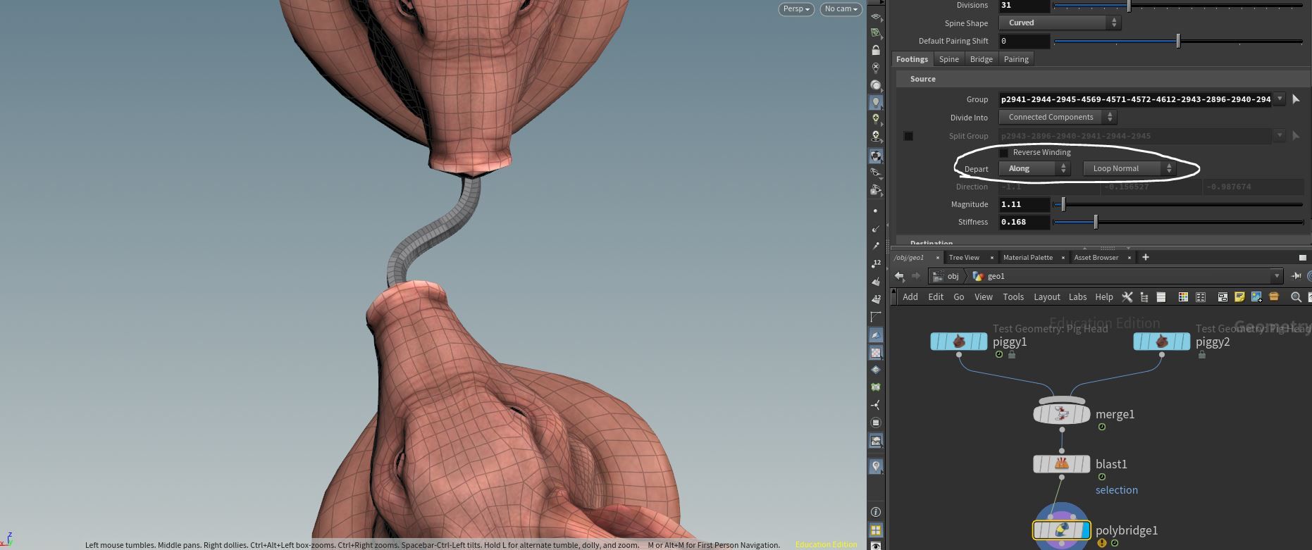
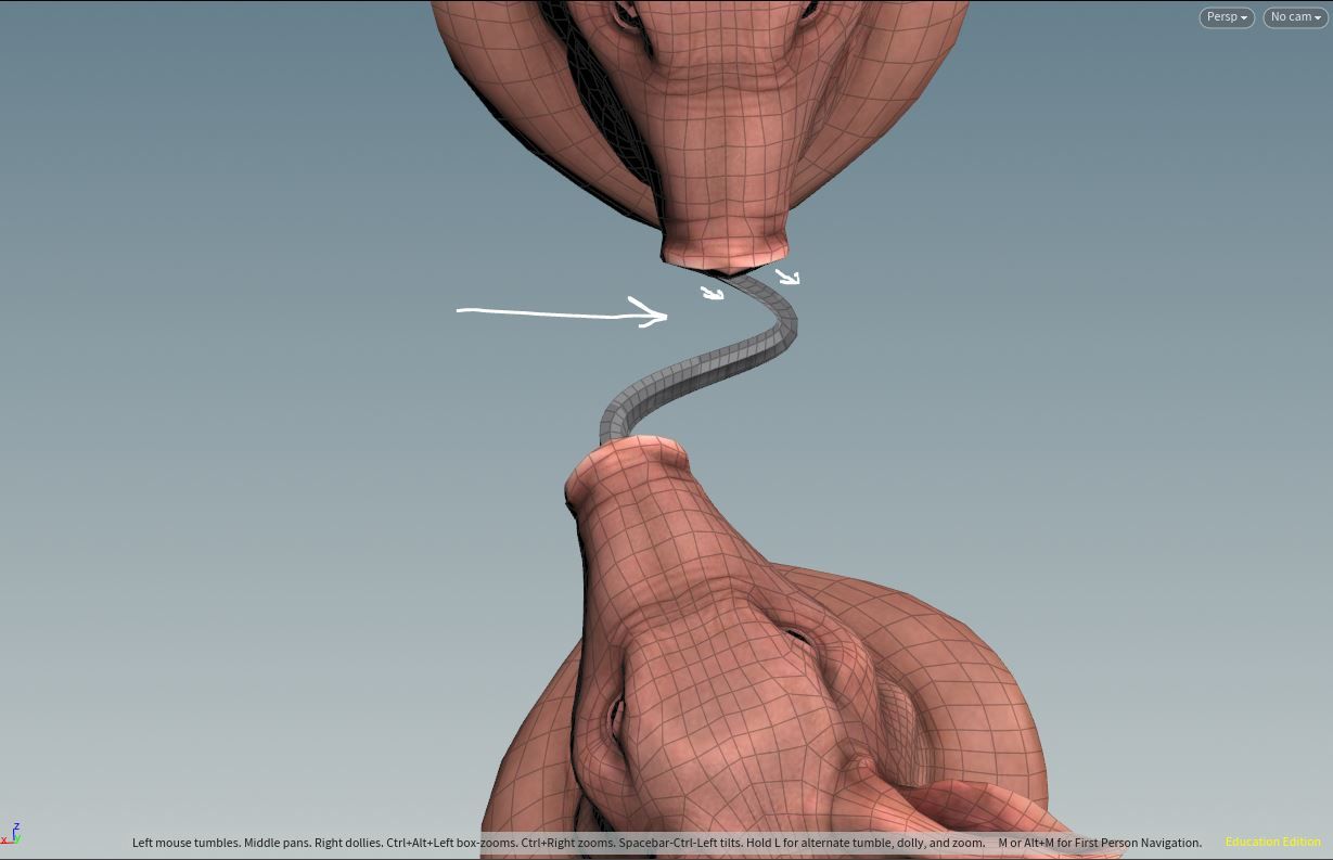
Depart:
-- This option is only available when "Curved" or "Curve from Second Input" is selected. This parameter will determine the initial direction that the curve is heading towards. By default, you have "Auto using" ... which is what you'll want for the majority of situations. The other option you may want to consider is "opposite" which will go in the opposite direction of whatever you specify next...
-- Loop Normal = The curve will start heading in the direction that's specified by the curve normal
-- Explicit Direction = The curve will start heading in a direction that you specify. See below for what it looks like when you have the Loop Normal vs. Explicit direction:
Spine:
Sample Points:
Bridge:
Bridge Mesh:
Generate Bridge Mesh:
-- You don’t need to create a mesh when bridging. This may be useful is you’re just trying to generate Spine Sample Points.
Mesh Group:
-- This will group the bridged polygons according to what you specify here.
Attach to Input Geometry at Source + Destination:
-- If you turn this off, then it will detach from the source or destination.
Clip Start + End:
-- This will allow you to remove the mesh from the start or end
Miter Joints:
-- This parameter is designed to improve the pinching that occurs at sharp angles. In general, I would suggest keeping this on, however, you can get a slightly different result by turning it off.
Normals:
Add Vertex Normals:
-- This is essentially the same as adding a “normal” node to the new bridged mesh. For more info on Normals, please visit the Normal Node Bible Entry.
Cusp All Source + Destination Boundary Edges:
-- This will ensure that the normals will not smooth in the areas which connect to the start or end of the bridged mesh.
Texture Coordinates:
Generate Unwrapped Texture Coordinates:
-- This will provide default uvs for the bridged mesh. Keep in mind that these uvs aren’t great, and its probably better to output a group from the poly extrude and the labs autouv node set to “UV AutoSeam”
Style:
-- Proportional = There is no documentation for this parameter, however, it appears that the UVS are placed into a rectangular uv island.
Thickness:
-- If you’d like to change the thickness of the extruded mesh, then you can do so here. The thickness is controlled by a ramp, and it also gives you the option of exporting an attribute which keeps track of the thickness scale along the mesh.
Pairing:
Twist:
Full-Turn Twists:
-- This will allow you to twist the extruded polygons by a certain number of twists.
Local Twist Attribute:
-- The attribute keeps track of how many times the mesh has been twisted along the bridged polygons. You can re-name this attribute by typing something besides “twist” if you’d like.
Local Twist Ramp:
-- According to the docs, “Controls the twist of the bridge along its length. The horizontal axis represents the length of the bridge. Values of 0.5 represent no twist. Values less than 0.5 twist in one direction, values greater than 0.5 twist in the other direction.” So, going down from 0.5 will twist in one direction, and going above 0.5 will twist in the other direction.
Interpolation:
-- According to the docs, “A technical parameter of the node’s internal algorithm. ‘Rotating frame’ tends to be better for twisting bridges, but in practice there’s no good basis for choosing one or the other. You can try both and see if they make a difference for your bridge.”
Implicit Pairing:
-- According to the docs, “A technical parameter of the node’s internal algorithm. Controls how the node pairs up points other than the initial pair and any explicit pairs. Changing this will often have no effect on the bridge.” ¯\_ (ツ)_/¯

Featured links

About Mentorship Calls
As a premium subscriber, you'll receive an email once a month with all the info necessary to schedule your call.
Study Plan Call
Look at the welcome email for further instructions on how to schedule a call if you are a Premium Subscriber.
Premium Member Discord
Unlike the standard discord server, the Premium Member server receives faster replies, feedback on projects outside CG Forge courses, and exclusive discounts on mentorship calls that aren't offered anywhere else.
Houdini Education License
In summary, the educational license of Houdini acts much like Houdini Indie - but at a discounted price. The main difference between Indie and Education is that this version of Houdini cannot be used for commercial projects. It's great, however, for learning and preparing a demo reel without the limitations of Houdini Apprentice.
Unlock Resources
One of the best examples of this is the Node Bible. This resource acts like an encyclopedia of Houdini knowledge. Each entry features a node, goes through all the parameters, and offers video quick tips on how to use each node. The Node Bible goes beyond the native Houdini documentation because it's easier to understand, offers practical examples, and links up to nodes that get used in the courses.
In the resource sections, you'll also find quick tips that cover a variety of miscellaneous topics along with The Weekly Wrangle - which is a series dedicated to advice and real-world conversations surrounding career success.
Redshift Discount
https://www.maxon.net/redshift
Aug 28th, 2024 Changelog
General Changes:
• New, simplified website design is now live!
◦ All new particle banner is featured on the home and after login pages
◦ The after-login page now features courses that are sorted by ones that you have recently watched. This makes it easier to continue watching whatever you’ve been working on without scrolling through all the courses to find what you’re looking for.
◦ There is also a new “resources” section that can be found beneath the “Browse Courses” on the after-login page. This makes it easier to bring up the Node Bible, the “Tips + Tricks,” or Weekly wrangle in a new tab
◦ “CG Forge Academy” has been replaced with a “Mentorship Calls” at the top menu (see below for more details)
◦ The resources dropdown now features “Tips + Tricks” (see below for details)
◦ Certification requirements have been slightly re-written to be easier to understand
◦ Subscriptions have been re-designed from the ground up (see below for details)
Subscription Changes:
• Subscriptions have changed to include a "Basic Subscription" and a "Premium Subscription" option. The Basic Subscription renews monthly, and the “Premium Subscription” renews every 4 months. Yearly subscriptions have been removed.
◦ These changes only affect new subscribers. Existing subscribers will not see anything change with their auto-renewal amount.
◦ 10% off a Redshift yearly subscription is now included with the Premium Subscription. (If you are currently a 4 or 12 month subscriber, then just email support@cgforge.com for this)
◦ A new “Study Plan” call has been added to the Premium Subscription. (If you are currently a 4 or 12 month subscriber, then just email support@cgforge.com for this)
◦ A Houdini education license is now available for “Premium” subscribers. (If you are currently a 4 or 12 month subscriber, then just email support@cgforge.com for this)
◦ For more information, visit the subscriptions page.
• CG Forge Academy has been redesigned to be easier to use.
◦ 45 minute calls have been removed. Existing coupons are still valid and can be used towards 90 minute sessions for the amount listed on each coupon.
◦ 8 week mentorships have been removed - Instead, you can book as many 90 minute calls as you’d like.
◦ Free onboarding calls have been removed - Instead, premium subscribers now receive a complimentary “Study Plan Call” that establishes a personalized curriculum moving forward.
◦ The “CG Forge Academy” top menu is now replaced with “Mentorship Calls” and only allows for booking 90 minute calls.
All new “Tips and Tricks” resource page:
• “Tips and Tricks” is now a resource page that holds all quick tips, Houdini update videos, and other miscellaneous videos in one place. If you’re looking for “Quicktips Season One and Two” or "Houdini 19 Updates" they have now migrated over to the “Tips and Tricks” resource section.
Discord changes:
• The CG Forge Discord channel will now be divided into two categories: “Basic Members” and “Premium Members.” The premium member channel will be invite-only to premium subscribers or those who are currently enrolled in a 4 or 12 month subscription. If you eligible to join the premium discord channel, email support@cgforge.com for an invitation.
◦ Basic Discord members will no longer receive support for projects that are outside the topic of CG Forge courses.
◦ Premium Discord members will receive support for projects outside of CG Forge content
◦ Premium members will receive discounts on mentorship calls, and basic members will not.
◦ Premium members will have their questions / posts answered before basic members
◦ Early access to courses will now be exclusively provided to premium members via the discord channel.
If you have any further questions about these changes, feel free to email support@cgforge.com
Cheers,
- Tyler
1:1 Support and Feedback
Unlock ALL Courses
Instead of paying lots of money for ONE course, you can pay less for a library of courses.
With CG Forge, you can also count on highly refined content that's conveniently found in one place. This makes it easy to cut through the clutter of Houdini tutorials out there and make the most of your time while you learn.
Disturbance
"The disturbance force introduces small amounts of change, mimicking the effects of localized environmental change. This localized change in momentum cancels itself out over time, preserving the simulation’s general motion and overall shape."
In practice, disturbance is great at capturing smaller details in a pyro sim. It's not as great at capturing larger movements and details. Artists will often use disturbance to break up mushroom shapes that occur along the leading edges of smoke simulations or to add tiny bits of detail in general.
Disturbance has two primary modes: Block-based and Continuous. Block based gives you better control over how large the detailed shapes are. The block size is represented in meters, and the larger the size, the larger size the randomized forces are on the pyro. Continuous will provide a fuzzier, smaller-detailed look, and it is often better to use when trying to soften the overall look of a pyro simulation. Continuous mode can be useful when representing avalanches or areas of mist along a waterfall.