Path Deform
Visit the Node Bible
Path Deform
The first input is the geometry (eg. car, vehicle, or the driven object) and the second input is the curve, (the path you want the item to move along).
General Parameters:
Group:
– This is where you tell Houdini what part of the model you want to change. You can give it a name or list numbers to choose specific parts (like primitives, edges, points, or vertices). You can also use the "Reselect" button to pick parts directly on the screen. If you leave this blank, Houdini will change everything in the first input.
Group Type:
– This tells Houdini what kind of parts you're talking about in the Group field—whether it's primitives, edges, points, or vertices.
Curves:
– This is a set of curves in the second input that Houdini will use to shape (and move) the model.
Match Geometry to Curves using Piece Attribute:
– If turned on, Houdini will match pieces of the model to curves using an attribute (a label) that both the model and curves share.
Piece Attribute:
– This is the label that Houdini uses to pair each piece of the model with a curve. Each piece of the model is connected to a curve that has the same label.
Map and Deform - Mappings
Enable Deformation:
– If you turn this off, the model won’t change shape. This can be useful if you want to see how the capture area lines up with the original model before it gets changed.
Map Length Using:
–This lets you decide how to set the length of the changed model:
Fraction of Curve Length:
– Set the length as a part of the curve's length, from 0 to 1. For example, if you want the model to stretch along the entire curve, you’d choose this and set it to 1.
Fraction of Geo Length:
– Set the length as a part of the model’s original length, from 0 to 1. This keeps the model the same length by choosing this option and setting it to 1.
Distance:
– You can set the length in regular world units instead of relative measurements based on the geometry or curve.
End Position Offset:
– This sets how long the changed model is when placed on the curve, using the units you choose in the ‘Offset end using’ menu.
Override:
– This lets you replace the Length setting with an attribute from the curve.
Pos End Attribute:
– This is an attribute on the curve that decides the length for each part of the curve.
Offset Position Using:
– This lets you decide how to place (and therefore move!) the model on the curve:
Curve U Position:
– You can place the model on the curve by choosing a fraction from 0 to 1. A setting of 0 puts the model at the start of the curve, and 1 puts it at the end.
Fraction of Geo Length:
– You can place the model based on a fraction of its original length, where 0 puts the start of the model at the start of the curve, and 1 puts the end of the model at the end of the curve.
Distance:
– You can place the model by measuring along the curve in world units.
Position Offset:
– This adjusts where the model starts on the curve, using the units you pick in the ‘Offset position using’ menu.
Override:
– This lets you replace the Position Offset with an attribute from the curve.
Pos Offset Attribute:
– This is a label on the curve that decides where to start the model for each part of the curve.
Uniform Scale:
– This sets how much to resize the model before placing it on the curve.
Enable Attribute Scale:
– This lets you replace the Uniform Scale with an attribute from the curve.
Uniform Scale Attribute:
– This label on the curve adjusts how much to resize the model for each curve, combining it with the base Uniform Scale to get the full amount of resizing.
Preserve Volume:
– If turned on, this keeps the model’s volume the same even after resizing it.
Start Behavior:
– This, along with End Behavior, decides what happens if the model goes beyond the curve. The best options for performance are Extend or Clamp.
Extend:
– The model keeps stretching past the curve's end.
Clamp:
– The model is stopped at the curve’s end, which might squash it if it tries to go beyond. This can cause parts of the model to overlap.
Clip:
– Any part of the model that goes past the end of the curve gets cut off, and new edges or points are created where needed. This is slower but can be more accurate than Extend or Clamp.
End Behavior:
– Works the same as Start Behavior but for the other end of the model.
Map and Deform - Geometry Deformations
Taper:
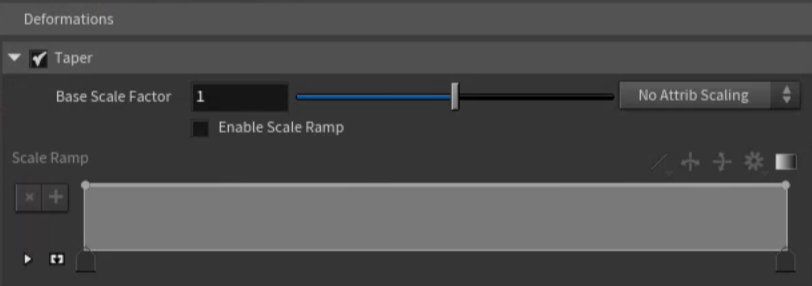
– This adjusts the size of the model using the Base Scale Factor and possibly a scale ramp (slider). Even though the model’s length is controlled by other settings, this will change its size in other directions, making it bigger or smaller.
Base Scale Factor:
– When scaling is turned on, this decides how much to grow or shrink the model from the curve. For example, a value of 1.0 keeps the model the same size, values less than 1.0 make it skinnier, and values more than 1.0 make it wider.
Enable Attribute Scale:
– This option lets you scale the model differently at different points along the curve by using an attribute (label) on the curve. It multiplies the Base Scale Factor by the ramp.
Curve Attribute:
– If you set the scaling to use an attribute from the curve, this is the name of that attribute. It decides how much to scale at each point on the curve.
Enable Scale Ramp:
– When this is on, the Base Scale Factor is also adjusted by a ramp for more control over the scaling.
Scale Ramp:
– When scaling with a ramp is on, this ramp (slider) lets you control how the model’s size changes along the curve. The vertical axis controls how much the model scales, and the horizontal axis represents the length of the curve.
Rotate:
– This lets you rotate or twist the model around its Forward direction, based on the Base Rotation and possibly a rotation ramp (slider).
Base Rotation:
– When rotation is turned on, this is the number of degrees the model rotates. For twisting instead of full rotation, use the ramp. If this value is set to 0, there will be no rotation.
Enable Attribute Scale:
– This option lets you rotate the model differently at different points along the curve by using an attribute (label) on the curve. It multiplies the Base Rotation by the ramp.
Curve Attribute:
– If you set the rotation to use an attribute from the curve, this is the name of that attribute. It adjusts how much rotation happens at each point along the curve. Note that if the Base Rotation is set to 0, no rotation will happen.
Enable Rotation Scale Ramp:
– When this is on, the Base Rotation is also adjusted by a ramp for more control over the rotation.
Rotation Scale Ramp:
– When rotation with a ramp is on, this ramp (slider) controls how the Base Rotation changes along the curve. The vertical axis controls how much the model rotates, and the horizontal axis represents the length of the curve. If Base Rotation is 0, no rotation will happen.
Rigidity:
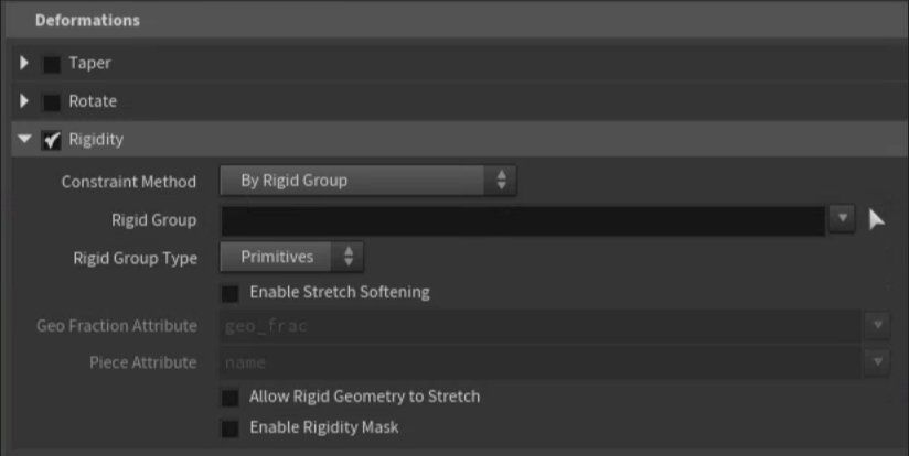
– When this is turned on, you can make certain parts of the model unbending or stiff (rigid).
Constraint Method:
– This decides how points on the model are mapped to the curve. If multiple points are mapped together, they will stay rigid in relation to each other.
By Rigid Group:
– You can choose specific rigid parts of the model by naming groups or using numbers for specific parts. See Rigid Group below for more details.
By Geometry Fraction Attribute:
– Use a point attribute on the model to manually control where each point should be deformed along the curve. See Geo Fraction Attribute below for more details.
By Piece Attribute:
– Use a piece attribute to specify which parts of the model should stay rigid.
Rigid Group:
– This is where you name a group or use numbers to pick specific parts of the model (like faces, edges, or points) that should be rigid. If you leave it empty, the entire model will be rigid, which is usually not what you want. Each connected part in this group will be treated as its own rigid piece. The point along the curve where it will map is based on the average position of the points in the group.
Rigid Group Type:
– This specifies what type of parts you listed in the Rigid Group (faces, edges, points, or corners).
Enable Stretch Softening:
– This smooths out the parts of the model that are near rigid areas, so they blend together better. Turn this on if you notice sharp transitions between rigid and non-rigid areas.
Soften Distance Metric:
– When softening is turned on, this decides how to measure the distance between rigid and non-rigid parts:
Edge:
– Measures the shortest path between points along the edges. This method is faster but less accurate.
Surface:
– Measures the shortest path across the surface of the model. This is slower but more accurate than the "Edge" method.
Soften Radius:
– This sets the distance from rigid points where the non-rigid points will be softened. The effect gets weaker the farther away a point is, and stops at the exact distance set by the soften radius.
Enable Falloff Ramp:
– Turn this on to control how the softening effect fades out, using a ramp (slider).
Soften Falloff:
– When the falloff ramp is turned on, this lets you control how the softening fades out. The left side of the ramp controls the softening at points closest to rigid areas, and the right side controls the softening at the edge of the soften radius.
Geo Fraction Attribute:
– For each point in the model, this attribute sets where along the curve the point should be placed, as a fraction of the curve's length (from 0.0 to 1.0).
Piece Attribute:
– This attribute defines how rigid pieces should behave. The average position of each piece’s parts decides where the piece is placed on the curve. The piece attribute can be a number or a word, and can apply to points or parts of the model.
Allow Rigid Geometry to Stretch:
– When this is on, rigid parts of the model can stretch along the curve just like non-rigid parts, but only in the forward direction.
Enable Rigidity Mask:
– This lets you control how rigid each part is, for example, by painting different levels of rigidity onto the model.
Base Rigidity Mask:
– This is the default rigidity for rigid parts. You can use an attribute to change this value. For example, 1.0 means fully rigid, 0.0 means not rigid at all, and 0.5 is halfway. If you want all rigid parts to behave the same, set this without using an attribute.
Enable Attribute Scale:
– This lets you change the base rigidity using an attribute on the model. This can allow different areas of the model to have different levels of rigidity.
Geometry Attribute:
– When scaling by attribute is turned on, this is the name of the attribute on the model that controls the rigidity.
Capture and Align - Geometry Alignment
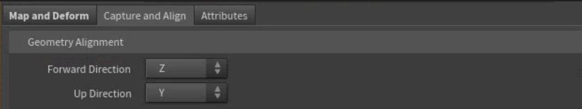
– This is the direction that defines the "facing" of the model. When the model is bent to follow a curve, it travels along this axis. The default direction is along the Z-axis (forward/back in depth).
X/Y/Z:
– The model is set up along one of the main directions (X, Y, or Z). The "front" of the model is assumed to point in the positive direction. If the model faces the negative direction (like pointing backward), you can use the Custom option to fix it. For example, if the front is facing the negative Z direction, pick Custom and set the direction to (0, 0, -1).
Custom:
– You can manually define the direction that represents the "depth" of the model by entering a custom vector.
Forward Axis Vector:
– If you chose Custom for the Forward direction, this is where you enter the vector (coordinates) that defines the model's length direction.
Up Direction:
– This is the direction that defines the "height" of the model. The node uses this to figure out how the model should be rotated or bent. The default direction is along the Y-axis (up/down)
X/Y/Z:
– The model has its "up" direction along one of the main axes (X, Y, or Z).
Custom:
– You can manually define the "up" direction of the model by entering a custom vector.
Up Axis Vector:
– If you chose Custom for the Up direction, this is where you enter the vector (coordinates) that defines the model's up direction.
Capture and Align - Curve Alignment
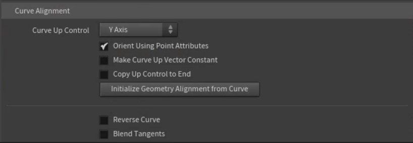
– This controls how the "up" direction is set for points along the curve. It can be changed by attributes on the points (explained below). By default, the "up" direction is slightly adjusted to stay perpendicular to the curve unless you choose to keep it constant (see Make curve up vector constant). The default direction is Y.
Curve Normal:
– Automatically picks the direction that is perpendicular to the curve’s plane if it was flat.
X/Y/Z:
– Sets the "up" direction along the positive X, Y, or Z axis. This is useful if your curve is drawn in one of these directions.
Custom:
– You can manually define the "up" direction of the curve by entering a custom vector.
Orient Using Point Attributes:
– When turned on, the node uses certain attributes on points to control how the model is oriented, rotated, or scaled along the curve. Supported attributes (which can be used in combination or alone) are:
• N
• up
• orient
• rot
• trans
• pivot
• pscale
• scale
• transform
Make Curve Up Vector Constant:
– Forces the "up" direction to stay constant as defined by the Curve Up Control. When this is off, the "up" direction is slightly adjusted to stay perpendicular to the curve. Keeping it constant might cause some distortion to the model.
Force Orthogonal Tangent:
– When Make Curve Up Vector Constant is on, turning this on prevents distortion by adjusting the curve’s tangent to stay at a right angle to the constant "up" direction. This helps keep the front of the model lined up correctly.
Copy Up Control to End:
– This makes the "up" direction at the start and end of the curve match the Curve Up Control. This is useful when you want the curve to form a loop.
Curve Up Vector:
– If you chose Custom for the Curve Up Control, this is where you enter the custom vector (coordinates) for the "up" direction.
Initialize Geometry Alignment from Curve:
– This sets up the model to follow the direction and orientation of the curve from the start. It automatically aligns the model’s forward direction, "up" direction, and starting position with the curve.
Reverse Curve:
– Reverses the direction of the curve, making the model follow it from the opposite end. This is handy if the curve was drawn the wrong way, and you don’t need to use another node to fix it.
Reverse N Attribute on Curve:
– Flips the N attribute (which controls the curve’s tangent) on the curve. This helps the node calculate how the curve bends.
Blend Tangents:
– Smooths the curve’s direction changes by averaging out the tangents.
Tangent Blend Strength:
– When Blend Tangents is on, this controls how strongly neighboring tangents influence each other. The default is 1.
Tangent Blend Iters:
– When Blend Tangents is on, this sets how many times the averaging process is repeated. The default is 10.
Capture and Align - Capture
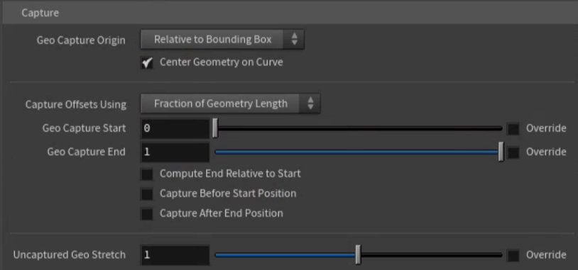
– This controls where the center of the capture region is. The capture region is like a box that wraps around your model. Normally, it’s centered on the model, but if you choose Custom, you can move the capture region away from the model’s center.
Note: It’s usually easier to leave this set to Relative to bounding box. You can use Geo capture start and Geo capture end to adjust the bending area. If you want to move the model away from the curve, turn off Center geometry on curve and move the model.
Relative to Bounding Box:
– Automatically centers the capture region at the middle of the model’s bounding box.
Custom:
– Lets you move the capture region along the Forward direction.
Center Geometry on Curve:
– When Geo capture origin is set to Relative to bounding box and this is on, the model’s bounding box center snaps to the curve. When off, the model stays in its original position, but will be offset from the curve.
Capture Origin Offset:
– The node acts like it's taking a flat plane along the Forward direction to capture geometry. If this plane starts past the geometry, the start won’t be captured. If the origin is before the start of the geometry, the model will be offset from the curve.
Capture Offsets Using:
– How to measure the start and end of the capture region:
Fraction of Geo Length:
– Offsets are given as percentages of the model's length.
Distance:
– Offsets are measured in world-space units.
Geo Capture Start:
– Moves the start of the capture region along the Forward direction. The part of the model before this point is extended but not bent along the curve.
Override:
– When turned on, lets you set Geo Capture Start using an attribute on the curves.
Capture Start Attribute:
– The name of a primitive attribute that controls Geo Capture Start for each curve.
Geo Capture End:
– Moves the end of the capture region. Anything beyond this point is extended but not bent along the curve.
Override:
– When turned on, lets you set Geo Capture End using an attribute on the curves.
Capture End Attribute:
– The name of a primitive attribute that controls Geo Capture End for each curve.
Compute End Relative to Start:
– As documented, when turned on, Geo Capture Start is added to Geo Capture End to calculate the end position. However, in the video, we find that this seems not to function as documented. Worth noting.
Capture Before Start Position:
– When turned on, the geometry before the start position is also captured.
Capture After End Position:
– When turned on, the geometry after the end position is also captured.
Uncaptured Geo Stretch:
– Controls how much to stretch geometry that isn’t captured by the curve. Perhaps useful as a diagnostic to see what is being captured and what isn’t?
Override:
– When turned on, lets you set Uncaptured Geo Stretch using an attribute on the curves.
Uncaptured Stretch Attribute:
– The name of a primitive attribute that controls Uncaptured Geo Stretch for each curve.
Attributes
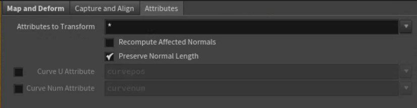
– Documented as: a list of attribute names or patterns. Any attributes that match these names are transformed along with the points in the geometry. The node will transform each attribute properly based on whether it’s a point, vector, or normal. However, in practice, there is an internal logic that seems not to transform arbitrary attributes in a way that can be seen in the geometry spreadsheet. Worth noting.
Recompute Affected Normals:
– This recalculates the normals of polygons that have both moved and unmoved points. If you’re transforming the whole geometry, you don’t need to worry about this. It only matters if you’re moving part of a connected piece, not all of it. This won’t work if P (the position attribute) isn’t included in Attributes to Transform.
Preserve Normal Length:
– Keeps the normal length the same during transformation.
Output Position Along Curve:
– When turned on, this creates a new attribute that tells you where each point is located along the curve, from 0.0 (start of the curve) to 1.0 (end of the curve).
Curve U Attribute:
– The name of the attribute where the position along the curve is stored.
Output Curve Num:
– When turned on, this creates an integer attribute that tells which curve segment (primitive) each point was mapped to.
Curve Num Attribute:
– The name of the attribute where the curve segment (primitive) number is stored.

Featured links

About Mentorship Calls
As a premium subscriber, you'll receive an email once a month with all the info necessary to schedule your call.
Study Plan Call
Look at the welcome email for further instructions on how to schedule a call if you are a Premium Subscriber.
Premium Member Discord
Unlike the standard discord server, the Premium Member server receives faster replies, feedback on projects outside CG Forge courses, and exclusive discounts on mentorship calls that aren't offered anywhere else.
Houdini Education License
In summary, the educational license of Houdini acts much like Houdini Indie - but at a discounted price. The main difference between Indie and Education is that this version of Houdini cannot be used for commercial projects. It's great, however, for learning and preparing a demo reel without the limitations of Houdini Apprentice.
Unlock Resources
One of the best examples of this is the Node Bible. This resource acts like an encyclopedia of Houdini knowledge. Each entry features a node, goes through all the parameters, and offers video quick tips on how to use each node. The Node Bible goes beyond the native Houdini documentation because it's easier to understand, offers practical examples, and links up to nodes that get used in the courses.
In the resource sections, you'll also find quick tips that cover a variety of miscellaneous topics along with The Weekly Wrangle - which is a series dedicated to advice and real-world conversations surrounding career success.
Redshift Discount
https://www.maxon.net/redshift
Aug 28th, 2024 Changelog
General Changes:
• New, simplified website design is now live!
◦ All new particle banner is featured on the home and after login pages
◦ The after-login page now features courses that are sorted by ones that you have recently watched. This makes it easier to continue watching whatever you’ve been working on without scrolling through all the courses to find what you’re looking for.
◦ There is also a new “resources” section that can be found beneath the “Browse Courses” on the after-login page. This makes it easier to bring up the Node Bible, the “Tips + Tricks,” or Weekly wrangle in a new tab
◦ “CG Forge Academy” has been replaced with a “Mentorship Calls” at the top menu (see below for more details)
◦ The resources dropdown now features “Tips + Tricks” (see below for details)
◦ Certification requirements have been slightly re-written to be easier to understand
◦ Subscriptions have been re-designed from the ground up (see below for details)
Subscription Changes:
• Subscriptions have changed to include a "Basic Subscription" and a "Premium Subscription" option. The Basic Subscription renews monthly, and the “Premium Subscription” renews every 4 months. Yearly subscriptions have been removed.
◦ These changes only affect new subscribers. Existing subscribers will not see anything change with their auto-renewal amount.
◦ 10% off a Redshift yearly subscription is now included with the Premium Subscription. (If you are currently a 4 or 12 month subscriber, then just email support@cgforge.com for this)
◦ A new “Study Plan” call has been added to the Premium Subscription. (If you are currently a 4 or 12 month subscriber, then just email support@cgforge.com for this)
◦ A Houdini education license is now available for “Premium” subscribers. (If you are currently a 4 or 12 month subscriber, then just email support@cgforge.com for this)
◦ For more information, visit the subscriptions page.
• CG Forge Academy has been redesigned to be easier to use.
◦ 45 minute calls have been removed. Existing coupons are still valid and can be used towards 90 minute sessions for the amount listed on each coupon.
◦ 8 week mentorships have been removed - Instead, you can book as many 90 minute calls as you’d like.
◦ Free onboarding calls have been removed - Instead, premium subscribers now receive a complimentary “Study Plan Call” that establishes a personalized curriculum moving forward.
◦ The “CG Forge Academy” top menu is now replaced with “Mentorship Calls” and only allows for booking 90 minute calls.
All new “Tips and Tricks” resource page:
• “Tips and Tricks” is now a resource page that holds all quick tips, Houdini update videos, and other miscellaneous videos in one place. If you’re looking for “Quicktips Season One and Two” or "Houdini 19 Updates" they have now migrated over to the “Tips and Tricks” resource section.
Discord changes:
• The CG Forge Discord channel will now be divided into two categories: “Basic Members” and “Premium Members.” The premium member channel will be invite-only to premium subscribers or those who are currently enrolled in a 4 or 12 month subscription. If you eligible to join the premium discord channel, email support@cgforge.com for an invitation.
◦ Basic Discord members will no longer receive support for projects that are outside the topic of CG Forge courses.
◦ Premium Discord members will receive support for projects outside of CG Forge content
◦ Premium members will receive discounts on mentorship calls, and basic members will not.
◦ Premium members will have their questions / posts answered before basic members
◦ Early access to courses will now be exclusively provided to premium members via the discord channel.
If you have any further questions about these changes, feel free to email support@cgforge.com
Cheers,
- Tyler
1:1 Support and Feedback
Unlock ALL Courses
Instead of paying lots of money for ONE course, you can pay less for a library of courses.
With CG Forge, you can also count on highly refined content that's conveniently found in one place. This makes it easy to cut through the clutter of Houdini tutorials out there and make the most of your time while you learn.
Disturbance
"The disturbance force introduces small amounts of change, mimicking the effects of localized environmental change. This localized change in momentum cancels itself out over time, preserving the simulation’s general motion and overall shape."
In practice, disturbance is great at capturing smaller details in a pyro sim. It's not as great at capturing larger movements and details. Artists will often use disturbance to break up mushroom shapes that occur along the leading edges of smoke simulations or to add tiny bits of detail in general.
Disturbance has two primary modes: Block-based and Continuous. Block based gives you better control over how large the detailed shapes are. The block size is represented in meters, and the larger the size, the larger size the randomized forces are on the pyro. Continuous will provide a fuzzier, smaller-detailed look, and it is often better to use when trying to soften the overall look of a pyro simulation. Continuous mode can be useful when representing avalanches or areas of mist along a waterfall.