
Edit
Visit the Node Bible
Edit
The Edit SOP is designed to interactively edit geometry components.
If you want to animate geometry, then use the transform, soft transform, peak, or soft peak nodes. The edit SOP is basically a package of many other nodes that have been put together to offer you a semi-destructive workflow.
In practice, here's what this means: Use the edit sop when you want to modify geometry components that don't need to be animated or rely on other attributes. Otherwise, a transform/soft transform/peak/or soft peak SOP is what you'll want to use.
Main Parameters:
Group/Group Type:
- Allows you to isolate the edit sop to a certain group of points/primitives. Read up on the Group SOP node bible entry if you're not familiar with groups yet. The Edit SOP is fairly unique though because the group field may change as you select various geo components. Each time you select new faces, the previous changes will be saved to the node and the group field will change to the latest selection.
Transform Order:
-- In what order would you like to apply the transformation? That means, are you going to scale first, then rotate, then translate? Or would you like the order of operations to be different? This parameter may be particularly relevant when rigging - especially when it comes to the order in which something is rotated.
Translate:
-- Moves your geo around in x,y,z
Rotate:
-- Rotates your geo in x,y,z
Scale:
-- Scales your geo in x,y,z
Shear:
-- Shear is typically used to calculate the Scale of something when using a 4x4 matrix. Here you can specify any additional shear, but in practice, this doesn't get used very often... or much at all really.
Pivot Transform:
-- This changes where the pivot is located. This is especially important when rotating because it will rotate everything relative to the pivot's location and rotation. To manually change this, you can press "insert" on the keyboard, move around the handle in the viewport to where you want the pivot to go, and then press "insert" again to exit pivot edit mode. In addition, the Edit SOP will automatically change these values to exist at the center of your selection when the "Transform Space" under "Transform Space Settings" is set to "Global."
Pre-Transform:
-- This area is particularly useful for rigging because it allows riggers to set a certain position, rotation, and/or scale as the "rest" or "zero" state for that object. In other words, it's like a transform that you do to something before the animator's transform is applied. This might be useful for, let's say, a rigger to bring something back to its rest pose by taking the difference between the current transform and the rest transform.
Local Pivot Transform:
-- There is no documentation on this parameter. However, this will become available when you set the "Transform Space" to Local Frame, Local Frame by Connectivity, or Local Origin by Connectivity. When any of those modes are selected, this field acts like a pre-transform on the pivot and behaves just like the Pivot Transform mentioned above.
Local Pre-Transform:
-- There is no documentation on this parameter. However, this will become available when you set the "Transform Space" to Local Frame, Local Frame by Connectivity, or Local Origin by Connectivity. When any of those modes are selected, this field acts like a pre-transform on the selected geometry and behaves just like the Pre-Transform mentioned above.
Preserve Normal Length:
-- If "Recompute Normals" is turned off, then this parameter becomes available. It seems to be bugged, however, because according to the docs it says, "Preserve normal lengths when re-computing point normals (when Re-compute point normals is on." This is rather odd because in order to re-compute the normals, the "Re-compute Normals" needs to be turned off for this option to be available. In general, I wouldn't worry yourself too much about this parameter in 99% of situations.
Transform Space:
-----------------
The transform space is asking you how it should calculate the transform data. It can do so Globally, which means that the transform values will exist in global space. As an example, the pivot translate will exist in global x,y,z values. If you were to do this with any of the "Local" settings, however, then the pivot translate values would be relative x,y,z values to the selection.
In the user docs, it refers to "Group Local" and "Local Per Island." However, these parameters do not exist. Instead, you will find "Local Frame," "Local Frame by Connectivity," and "Local Origin by Connectivity." Anything that is "local" means that the transformation exists relative to a selection of components. Frustratingly enough, you will not find user documentation on "Local Frame by Connectivity" or "Local Origin by Connectivity." The information below will hopefully offer a better explanation.
-----------------
-- Global = The transform values are generated in global x,y,z space. The gnomon is automatically set to the center of your selection and the orientation is the average orientation of the selected components.
-- Local Frame = Use this setting if the Global setting did not give you what you wanted in the gnomon orientation. The term "Frame" here can be better understood as a construction plane that's based on your selection. How it generates this "Frame" is determined by the Local Frame parameter options:
** Component = it figures out your pivot by looking at the center bounding box of your selection. It then looks at the average local space orientation of all your components to figure out how the pivot is oriented.
** Normal + Vector = The gnomon is placed at the center of the bounding box and the local space orientation is determined by the average normal and a world space Up Vector. Note that this Up vector is defined in the "Up Vector" parameter. For more information about up vectors and orienting things, visit the Quaternions & Matrices Course.
** Oriented Bounding Box = An oriented bounding box is computed with the local space origin and orientation being determined by that oriented bounding box.
-- Local Frame by Connectivity = This will allow you to rotate multiple areas of selection independently from one another. In my head, I imagine multiple construction planes being placed on each island of selected components. When you transform something in this mode, it does it independently for each island. Soft Selection is not available in this mode.
-- Local Origin by Connectivity = This is the same thing as Local Frame except that the gnomon orientation is defined by the last selected island of components. Unlike the Local Frame by Connectivity, this mode will not create independent orientations for each island. Note that the Local Frame parameter is not available. Soft selection is also not available.
Slide on Surface:
-- This allows you to slide your transformation along the mesh's existing surface.
Commit Transform/Peak Changes:
-- This will save the current edit and reset the parameters to start a new edit.
Soft Settings:
------------
The Soft Selection is available when selecting points and offers a way of feathering out transformations.
------------
Distance Metric:
-- This determines how the soft radius is measured outwards.
-- Attribute, Apply Rolloff, and Distance Attribute = Allows you to use a point attribute to tell the points how much the transformation is allowed to affect it. A value of 0 says, "The transform is not allowed to affect this point." A value of 1 says, "Apply the full transformation to this point." The "Apply Rolloff" parameter will, in practice, blur out the attribute values. Remember that you can set the Soft Radius beyond 1 for more of the falloff. Also, keep in mind that if your attribute values go beyond 1, then you'll get unpredictable results.
-- Edge = The soft selection figures out how to transform surrounding points based on the shortest distance to a point in the group following a path along edges. In practice, this will make sure that your soft selection does not affect other disconnected pieces of geometry.
-- Radius = Imagine blowing up a sphere which controls how much influence the soft selection is allowed to have. That's how soft selection will be determined. Use this if you want to select disconnected pieces of geometry.
-- Radius With Connectivity (depreciated) = Don't use this because it's depreciated.
-- Surface = This does the same thing as "edge" mentioned above. The difference here though is that the soft radius isn't reliant on the topological direction of edges. It just calculates distance based on a path along the surface.
Lead Point Attribute:
-- This parameter is not available when using the Edit SOP because it relies on a setting called "Translate Along Lead Normal" which does not exist within the Edit node parameters...
Soft Radius:
-- How far out the soft radius is allowed to go.
Soft Type:
-- This provides a different falloff for the in-between areas of the soft radius. (In other words, it changes how quickly something goes from 1 to 0... from full to no effect....). Play around with these parameters if you're not happy with how quickly the falloff is occurring.
Tangent Angles:
-- Available when the "Soft Type" is cubic. According to the docs: "Angles of the cubic rolloff function’s tangents. The first value applies to the tangent farthest from the source point, the second applies to the tangent closest to the source point." If you understand the specifics of this algorithm, then perhaps you'll know how to use this parameter. If you don't understand the algorithm, then you'll notice that adjusting the values will change the falloff surrounding the selection. In practice, you can just adjust these parameters until the falloff is close to what you want it to be.
Kernel Function:
-- Available when the "Soft Type" is set to Meta-ball. These provide different falloffs to choose from.
Visualize Falloff:
-- Allows to adjust viewport visualization of the soft falloff.
Mirror/Orient Settings:
Use Orient Attribute:
-- This allows you to use the @orient attribute to keep your transformations relative to any quaternion rotations which may be present on the geometry. To learn more about @orient and quaternions, please visit the Copy To Points node bible entry along with the Quaternions and Matrices course.
Use Mirror:
-- Allows you to mirror any transformations across a plane which you define using Axis, Origin, Distance, Threshold, and Plane Tolerance.
Axis:
-- If you want to mirror in the X axis, then you'll set this parameter to 1,0,0 ... mirroring in Y would be 0,1,0 and Z is 0,0,1.
Origin:
-- This allows you to offset the mirror plane. In practice, I typically set this to the bbox center of the object if the geo does not exist on the origin. You can do so by right clicking the text of this parameter --> Reference --> Scene Data --> Select the node above the edit --> Bounding Box --> Centroid
Distance:
-- According to the docs, "This is the distance of the plane of symmetry from the origin of symmetry. In practice, I haven't found a practical use for it.
Threshold:
-- According to the docs. "This is the maximum distance from a point's mirrored position to search for the mirrored point." However, this seems to be bugged because even an object that's scaled up to 100 x 100 x 100 meters will still recognize the mirrored action. So, again, in practice, this seems to have little to no use.
Plane Tolerance:
-- This setting figures out how close a point needs to be to the mirror plane before it snaps it directly onto the mirrored plane. The defaults ought to work just fine for most situations.
Peak Settings:
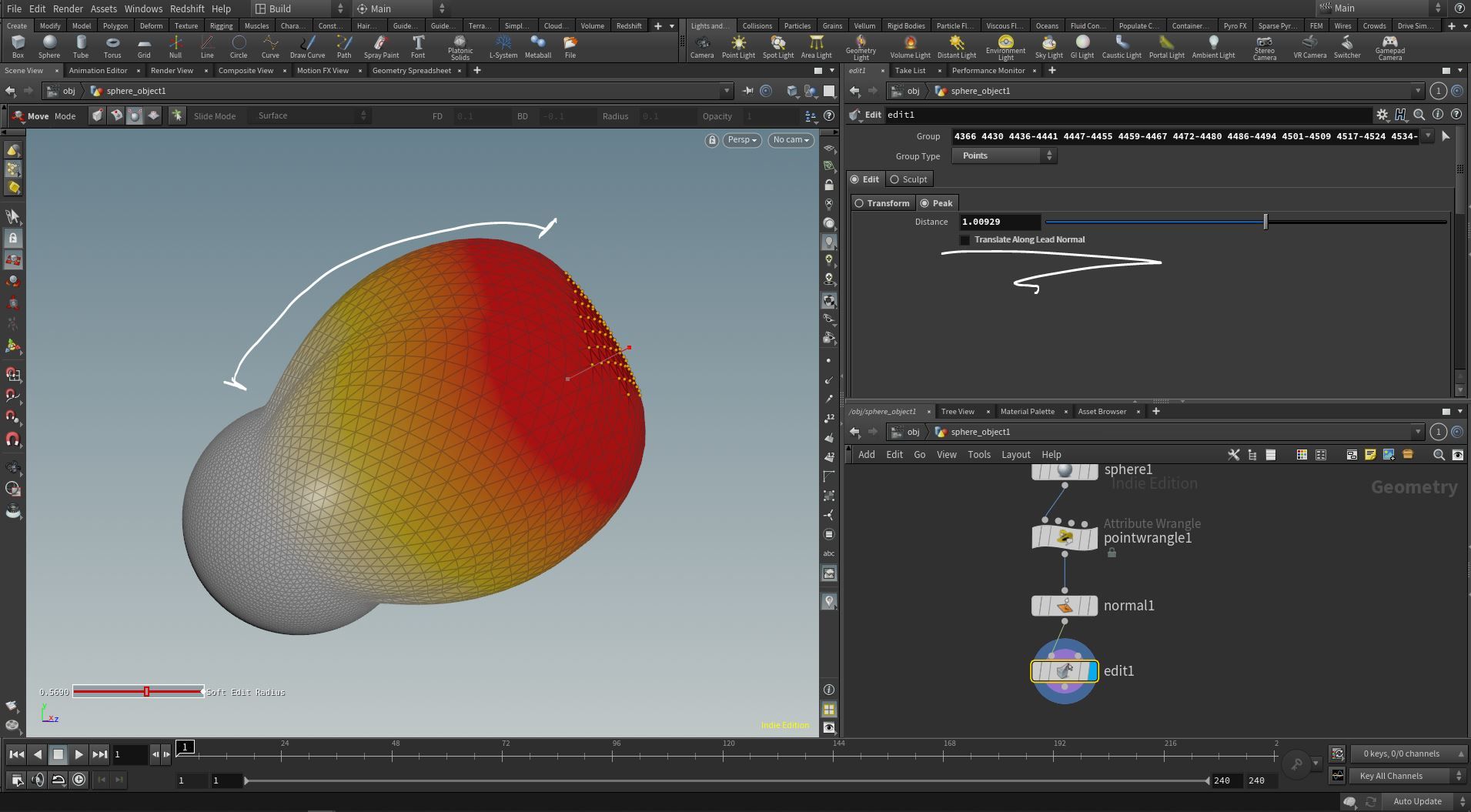
Distance:
-- The Peak allows you to transform your selection in the direction of its normal. The distance is how far it should go.
Translate Along Lead Normal:
-- This setting is only available if you first engage soft selection. If you leave this on, then the peak distance will create a straight line outwards from the transform. If you turn this off, then it will round out the soft select areas when applying the distance. See the example below:
Sculpt Settings:
----------------------------------------
If this mode is enabled, then you can sculpt onto the mesh. These settings control the behavior of the sculpting brush. To activate this in the viewport, hover over the viewport and press enter. If this does not work, then create a brand new edit sop and try again. -- Caution -- If you have any serious sculpting work that needs to get done, then do it in Zbrush or Blender. The Edit SOP is not designed for capturing a good sculpting workflow and can be very buggy. It's only useful if you want to do a few basic touchups on something.
----------------------------------------
Operation:
----------------------------------------
----------------------------------------
This section controls how the brush should behave. NOTE - If you change settings in the parameter window, those settings will not apply to future strokes that you do in the viewport. It's always better to right mouse in the viewport and select what you want there.
--------------------
Goal:
-- Deform Points = Points will move in or out.
-- Smooth = Averages point positions
-- Deform & Smooth = Does as it says
-- Erase Changes = Reverts an area back to the state something was before edit sop made any changes.
Axis:
-- Normal = When deforming points, it will move the points in the normal's direction
-- X,Y, or Z = When deforming points, the Edit sop will move point in this direction.
-- User Defined/Vector Field = When deforming points, the Edit SOP will move points in the direction specified in the "Vector" field.
Accumulate to Stencil & Apply and Clear Stencil:
-- According to the docs, "By default, the operation is applied and the stencil cleared after every brush stroke. With this set, the stencil is not cleared until "Apply and Clear Stencil" is pressed."
Here's another way of saying that... the accumulate to stencil makes it so that brush stroke isn't complete until you press the "Apply and Clear Stencil" button. Normally your brush stroke is done when you let go of the mouse. This is like keeping the mouse held down until you press the button.
Update Displacement Normals:
-- This will re-compute the sculpting normals used by the sculpting operation. NOTE this is not the same thing as using a normal SOP after the edit. The edit node will not update your viewport normals after each stroke unfortunately. For this reason, I would recommend setting a normal node after the edit sop to see updated viewport normals. It is faily unclear as to what the "sculpting normals" are referring to - with my best guess being the normals that are internally understood by the edit sop when sculpting along the surface.
Apply to All:
-- Applies the sculpting operation to all points. This may be especially useful when you want to smooth everything.
LMB Displacement:
-- How far to deform points when using left-mouse
MMB Displacement:
-- How far to deform points when using middle-mouse. In practice, I can't get this to work.
----------------------------------------
----------------------------------------
Brush:
----------------------------------------
----------------------------------------
The brush section deals with the brush settings in the viewport. Unlike the Operation Tab, any changes you make in this tab will reflect in the viewport properly.
----------------------------------------
Shape/Bitmap:
-- Defines the brush shape. The bitmap option will become available below if you decide to use a stencil for your brush shape.
-- This tells Houdini which color channel it should look at when using a texture map for the brush shape. By default it's "Alpha" but I would recommend Luminance as a better default. Many images don't have an alpha channel, so just be sure to clearly specify which color channel is going to be used for the black/white values.
-- This defines how large your brush is.
UV Radius:
-- If you were to use a brush in a UV viewport pane, then this would be the size of the brush in uv space. This doesn't make much sense for the Edit SOP however and I would generally ignore it.
-- How sensitive should the pressure be on a tablet? A high value is less sensitive to pressure. Lower values are more sensitive to pressure.
-- Some operations can benefit from a 3d brush. Altering hair curves may be a scenario where depth sculpting may be useful. Enabling depth will turn your surface brush into a 3d one. The first field is asking you how far into the surface it's allowed to go. The second field is asking you how far away from the surface the brush is allowed to go.
-- According to the docs, "How far to rotate the brush." In order to understand what this actually does, you'll need to change the up vector type to "Fixed" and add some brush squash to change the shape. Once you do that, the Brush angle will rotate the brush and you'll be able to notice a difference.
Brush Squash:
-- Changes the shape of the brush and squashes it.
Opacity:
-- When using a stencil, this will essentially alter the intensity of the brush operation.
-- If this is set to 1, then the pressure from your tablet is allowed to affect the intensity of the brush stroke. If it's set to 0, then you'll get the full opacity right away.
Brush Splatter:
-- Adds a noise to the intensity of the brush stroke. The position of the brush will change the noise pattern
Paper Grain:
-- This also adds a noise. This time the noise changes based on object position.
-- This feathers the brush intensity on the inside of the brush radius.
-- This Kernel affects the falloff that's used inside the brush when it goes to falloff.
Up Vector Type:
-- This orients the brush. The stroke direction will cause your brush to rotate based on the direction that it's moving in. You can be more specific though by choosing "Fixed" instead. If that's the case, then you'll need to specify an up vector telling the brush how it ought to rotate.
----------------------------------------
----------------------------------------
Orient Brush To Surface:
-- This will do just as it says. The brush will follow along the surface as you hover over it in the viewport. There may be situations where you'll want to turn this off, however. If you want to edit points or apply paint based on your view rather than the current shape of the surface, then you might want to turn Orient Brush To Surface off.
Use Connectivity:
-- "If set, the tool will only affect points connected to the closest point to the intersection. This is usually a good thing, as it avoids accidentally painting through the geometry (see the depth parameter), but can prevent smoothly painting across seams."
Use Normals:
-- There is no documentation, so the use of this option is unclear.
Realtime Node:
-- Applies changes as you brush (that is, while you are still holding the mouse button down) instead of at the end of each stroke. This is less efficient, but lets you do things like paint on surfaces while playing the animation. I'm not sure why you would want to paint something during an animation, but alas, it is possible. Keep in mind that the quality of the brush stroke goes way down though.
Direction, Hit Location, Hit Primitive, Hit UVW, Hit Pressure, Hit Point, and Event:
-- All these settings are here to capture data as you paint. They are not parameters that you will adjust manually in the parameter window. In practice, you don't need to concern yourself with this. Have a look at the user docs if you're curious about what these do though.

Featured links

About Mentorship Calls
As a premium subscriber, you'll receive an email once a month with all the info necessary to schedule your call.
Study Plan Call
Look at the welcome email for further instructions on how to schedule a call if you are a Premium Subscriber.
Premium Member Discord
Unlike the standard discord server, the Premium Member server receives faster replies, feedback on projects outside CG Forge courses, and exclusive discounts on mentorship calls that aren't offered anywhere else.
Houdini Education License
In summary, the educational license of Houdini acts much like Houdini Indie - but at a discounted price. The main difference between Indie and Education is that this version of Houdini cannot be used for commercial projects. It's great, however, for learning and preparing a demo reel without the limitations of Houdini Apprentice.
Unlock Resources
One of the best examples of this is the Node Bible. This resource acts like an encyclopedia of Houdini knowledge. Each entry features a node, goes through all the parameters, and offers video quick tips on how to use each node. The Node Bible goes beyond the native Houdini documentation because it's easier to understand, offers practical examples, and links up to nodes that get used in the courses.
In the resource sections, you'll also find quick tips that cover a variety of miscellaneous topics along with The Weekly Wrangle - which is a series dedicated to advice and real-world conversations surrounding career success.
Redshift Discount
https://www.maxon.net/redshift
Aug 28th, 2024 Changelog
General Changes:
• New, simplified website design is now live!
◦ All new particle banner is featured on the home and after login pages
◦ The after-login page now features courses that are sorted by ones that you have recently watched. This makes it easier to continue watching whatever you’ve been working on without scrolling through all the courses to find what you’re looking for.
◦ There is also a new “resources” section that can be found beneath the “Browse Courses” on the after-login page. This makes it easier to bring up the Node Bible, the “Tips + Tricks,” or Weekly wrangle in a new tab
◦ “CG Forge Academy” has been replaced with a “Mentorship Calls” at the top menu (see below for more details)
◦ The resources dropdown now features “Tips + Tricks” (see below for details)
◦ Certification requirements have been slightly re-written to be easier to understand
◦ Subscriptions have been re-designed from the ground up (see below for details)
Subscription Changes:
• Subscriptions have changed to include a "Basic Subscription" and a "Premium Subscription" option. The Basic Subscription renews monthly, and the “Premium Subscription” renews every 4 months. Yearly subscriptions have been removed.
◦ These changes only affect new subscribers. Existing subscribers will not see anything change with their auto-renewal amount.
◦ 10% off a Redshift yearly subscription is now included with the Premium Subscription. (If you are currently a 4 or 12 month subscriber, then just email support@cgforge.com for this)
◦ A new “Study Plan” call has been added to the Premium Subscription. (If you are currently a 4 or 12 month subscriber, then just email support@cgforge.com for this)
◦ A Houdini education license is now available for “Premium” subscribers. (If you are currently a 4 or 12 month subscriber, then just email support@cgforge.com for this)
◦ For more information, visit the subscriptions page.
• CG Forge Academy has been redesigned to be easier to use.
◦ 45 minute calls have been removed. Existing coupons are still valid and can be used towards 90 minute sessions for the amount listed on each coupon.
◦ 8 week mentorships have been removed - Instead, you can book as many 90 minute calls as you’d like.
◦ Free onboarding calls have been removed - Instead, premium subscribers now receive a complimentary “Study Plan Call” that establishes a personalized curriculum moving forward.
◦ The “CG Forge Academy” top menu is now replaced with “Mentorship Calls” and only allows for booking 90 minute calls.
All new “Tips and Tricks” resource page:
• “Tips and Tricks” is now a resource page that holds all quick tips, Houdini update videos, and other miscellaneous videos in one place. If you’re looking for “Quicktips Season One and Two” or "Houdini 19 Updates" they have now migrated over to the “Tips and Tricks” resource section.
Discord changes:
• The CG Forge Discord channel will now be divided into two categories: “Basic Members” and “Premium Members.” The premium member channel will be invite-only to premium subscribers or those who are currently enrolled in a 4 or 12 month subscription. If you eligible to join the premium discord channel, email support@cgforge.com for an invitation.
◦ Basic Discord members will no longer receive support for projects that are outside the topic of CG Forge courses.
◦ Premium Discord members will receive support for projects outside of CG Forge content
◦ Premium members will receive discounts on mentorship calls, and basic members will not.
◦ Premium members will have their questions / posts answered before basic members
◦ Early access to courses will now be exclusively provided to premium members via the discord channel.
If you have any further questions about these changes, feel free to email support@cgforge.com
Cheers,
- Tyler
1:1 Support and Feedback
Unlock ALL Courses
Instead of paying lots of money for ONE course, you can pay less for a library of courses.
With CG Forge, you can also count on highly refined content that's conveniently found in one place. This makes it easy to cut through the clutter of Houdini tutorials out there and make the most of your time while you learn.
Disturbance
"The disturbance force introduces small amounts of change, mimicking the effects of localized environmental change. This localized change in momentum cancels itself out over time, preserving the simulation’s general motion and overall shape."
In practice, disturbance is great at capturing smaller details in a pyro sim. It's not as great at capturing larger movements and details. Artists will often use disturbance to break up mushroom shapes that occur along the leading edges of smoke simulations or to add tiny bits of detail in general.
Disturbance has two primary modes: Block-based and Continuous. Block based gives you better control over how large the detailed shapes are. The block size is represented in meters, and the larger the size, the larger size the randomized forces are on the pyro. Continuous will provide a fuzzier, smaller-detailed look, and it is often better to use when trying to soften the overall look of a pyro simulation. Continuous mode can be useful when representing avalanches or areas of mist along a waterfall.