Ray
Visit the Node Bible
Ray
General Parameters:
Group:
-- This allows you to specify a selection of prims or points to be considered when reading geometry from the first input of the node.
Entity:
-- This relates to what kind of group you'd like to specify
Collision Group:
-- This is the group of prims or points to be considered when reading information from the second input of the node.
---------------------------------
Method:
Project Rays:
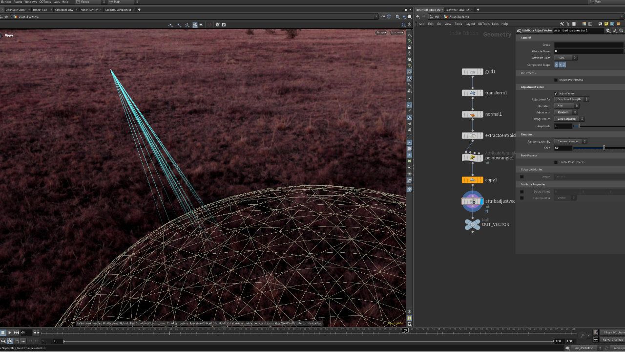
-- This method will cause the ray node to project rays away from the points or prims in a certain direction. If the rays hit something, it can then allow you to affect the geometry in some kind of way.
Minimum Distance:
-- This method will simply find the minimum distance between the two geometry streams. If you'd like to, for example, move points to the location that's closest to it from the the other geometry stream, this will do so.
--------------------------------------
Direction Source: (These options are only visible when the "Project Rays" is selected)
-- Vector
Sets a custom direction vector for the projection. You can think of this as specifying a direction from each point or prim in x,y,z for the ray to travel in. So, for example, a value of 0,1,0 would tell each point or primitive to send a ray in the +Y direction. By default, this uses an expression @N.[] to use the point normals of your geometry when sending rays. You can delete this if you'd like, and specify your own vector here.
-- Normal
Uses the point normals to define the projection direction.
-- Attribute
Allows you to use a custom vector attribute for direction, offering more control on a per-point basis. This attribute ought to be a vector attribute which describes which direction a specific point or prim ought to shoot a ray.
--------------------------------------
Direction Type: (These options are only visible when the "Project Rays" is selected)
-- Forward
Shoots the ray in the direction that's specified.
-- Reverse
Shoots the ray in the opposite direction specified.
-- Bidirectional
Shoots the ray in both the direction and opposite direction specified.
--------------------------------------
-- Show Guide Geometry
Displays a wireframe of the target collision geometry to help visualize how your projection interacts with it.
-- Transform Points
Enables actual transformation of the points. Disable this if you're only using the Ray SOP to transfer attributes or create groups.
-- Intersect Farthest Surface
By default, rays hit the closest surface. Enable this to project onto the **farthest** surface instead.
-- Ray Tolerance
According to the docs: "Controls the tolerance of the ray intersection. Due to numerical round off, otherwise watertight geometry might let rays pass through it. The ray tolerance decreases the chance of ray leakage by allowing near misses to count as hits. For very small geometry, you may want to decrease the default to avoid false positives. Likewise, very large geometry may need a higher value."
In practice, the ray tolerance is there to help with accuracy when dealing with very large or small objects. Only use if you're finding inaccurate results.
- Scale
This affects the positioning of an object that is casted onto another object. In effect, it allows you to undershoot or overshoot the position. In practice, this can be nice to use if you need a little bit of spacing between the two objects so that they're not perfectly on top of each other.
-- Lift
This is identical to the scale parameter except that it maintains the shape of the projected object. The scale act more like a blend between the original mesh and the projected mesh. This acts more like an offset because it doesn't change the shape of the projected geometry.
-- Bias
The user documentation does not include any info about the bias parameter. From what we can tell, this will allow you to enable / disable certain areas for projection.
-- Max Distance
This allows the rays to travel a max distance when searching for objects to hit. If an object is not within a certain distance, the ray node not affect the point/prim in any way.
-- Point Intersection Normal
Transfers normals from the collision geometry to the affected points on your projected geometry. In case you want good normals on your new geometry, it's best practise to add a normal node after the Ray node, with possible a reverse node in between (in case your normals are the wrong way around).
--------------------------------------
Samples: (This section will generally randomize the directions of each sample. In order to see any change, you need to increase the "Jitter Scale." In practice, it's usually easier to ignore this section and specify the directions yourself on the incoming geometry.)
This parameter creates a certain number of samples that are sent from each point/prim. With multiple samples shot out in random directions, the result of multiple samples are then combined into one ray sample via the "Combine Samples" method that is selected.
Jitter Scale:
This can generally be thought of as how much you want the rays to randomly change their direction. This value appears to be arbitrary, so it's best to adjust it yourself and see the result.
Seed:
Provides a different variation of randomization
Combine Samples:
When multiple rays are sent from each point/prim, this parameter determines how the final ray is determined. Average will return the average direction, median will find the median vector value, shortest finds the shortest vector that hit the other object, and longest finds the longest ray that was randomly shot outwards.
--------------------------------------
Output: (This section determines what sort of output attribute information is stored onto the resulting geometry)
-- Point Intersection Normal
There doesn't seem to be any documentation for this parameter. From what we can tell, checking this on will tell the collision geometry that it should replace it's original normals with the normals of the collision geometry.
-- Point Intersection Distance
Writes out an attribute containing the exact distance from each point (or primitive) to the collision geometry. Use this value when you need to drive custom effects or visualize how far each intersection traveled.
-- Ray Hit Group
If the projected ray from a point/prim hits the collision geometry successfully, then turning this on will include that point/prim within a group. If a point/prim does not hit the collis geometry, then it will not be included in this output group.
-- Prim Num Attribute:
This will create an attribute on the ray geometry that indicates the prim number of the collis geometry that it hit.
-- Prim UVW Attribute:
This will create an attribute that describes the location in the primitive's parametric space. This is different than the UV space. It refers to a parametric location that exists along the primitive that it hit. For more information on what parametric space means for primitives, visit the primitives chapter in Houdini Principles.
-- Import Hit Attributes
This section allows you to import the attributes found on the collision geometry.
-- Import Hit Groups
This section allows you to import groups found on the collision geometry.

Featured links

About Mentorship Calls
As a premium subscriber, you'll receive an email once a month with all the info necessary to schedule your call.
Study Plan Call
Look at the welcome email for further instructions on how to schedule a call if you are a Premium Subscriber.
Premium Member Discord
Unlike the standard discord server, the Premium Member server receives faster replies, feedback on projects outside CG Forge courses, and exclusive discounts on mentorship calls that aren't offered anywhere else.
Houdini Education License
In summary, the educational license of Houdini acts much like Houdini Indie - but at a discounted price. The main difference between Indie and Education is that this version of Houdini cannot be used for commercial projects. It's great, however, for learning and preparing a demo reel without the limitations of Houdini Apprentice.
Unlock Resources
One of the best examples of this is the Node Bible. This resource acts like an encyclopedia of Houdini knowledge. Each entry features a node, goes through all the parameters, and offers video quick tips on how to use each node. The Node Bible goes beyond the native Houdini documentation because it's easier to understand, offers practical examples, and links up to nodes that get used in the courses.
In the resource sections, you'll also find quick tips that cover a variety of miscellaneous topics along with The Weekly Wrangle - which is a series dedicated to advice and real-world conversations surrounding career success.
Redshift Discount
https://www.maxon.net/redshift
Aug 28th, 2024 Changelog
General Changes:
• New, simplified website design is now live!
◦ All new particle banner is featured on the home and after login pages
◦ The after-login page now features courses that are sorted by ones that you have recently watched. This makes it easier to continue watching whatever you’ve been working on without scrolling through all the courses to find what you’re looking for.
◦ There is also a new “resources” section that can be found beneath the “Browse Courses” on the after-login page. This makes it easier to bring up the Node Bible, the “Tips + Tricks,” or Weekly wrangle in a new tab
◦ “CG Forge Academy” has been replaced with a “Mentorship Calls” at the top menu (see below for more details)
◦ The resources dropdown now features “Tips + Tricks” (see below for details)
◦ Certification requirements have been slightly re-written to be easier to understand
◦ Subscriptions have been re-designed from the ground up (see below for details)
Subscription Changes:
• Subscriptions have changed to include a "Basic Subscription" and a "Premium Subscription" option. The Basic Subscription renews monthly, and the “Premium Subscription” renews every 4 months. Yearly subscriptions have been removed.
◦ These changes only affect new subscribers. Existing subscribers will not see anything change with their auto-renewal amount.
◦ 10% off a Redshift yearly subscription is now included with the Premium Subscription. (If you are currently a 4 or 12 month subscriber, then just email support@cgforge.com for this)
◦ A new “Study Plan” call has been added to the Premium Subscription. (If you are currently a 4 or 12 month subscriber, then just email support@cgforge.com for this)
◦ A Houdini education license is now available for “Premium” subscribers. (If you are currently a 4 or 12 month subscriber, then just email support@cgforge.com for this)
◦ For more information, visit the subscriptions page.
• CG Forge Academy has been redesigned to be easier to use.
◦ 45 minute calls have been removed. Existing coupons are still valid and can be used towards 90 minute sessions for the amount listed on each coupon.
◦ 8 week mentorships have been removed - Instead, you can book as many 90 minute calls as you’d like.
◦ Free onboarding calls have been removed - Instead, premium subscribers now receive a complimentary “Study Plan Call” that establishes a personalized curriculum moving forward.
◦ The “CG Forge Academy” top menu is now replaced with “Mentorship Calls” and only allows for booking 90 minute calls.
All new “Tips and Tricks” resource page:
• “Tips and Tricks” is now a resource page that holds all quick tips, Houdini update videos, and other miscellaneous videos in one place. If you’re looking for “Quicktips Season One and Two” or "Houdini 19 Updates" they have now migrated over to the “Tips and Tricks” resource section.
Discord changes:
• The CG Forge Discord channel will now be divided into two categories: “Basic Members” and “Premium Members.” The premium member channel will be invite-only to premium subscribers or those who are currently enrolled in a 4 or 12 month subscription. If you eligible to join the premium discord channel, email support@cgforge.com for an invitation.
◦ Basic Discord members will no longer receive support for projects that are outside the topic of CG Forge courses.
◦ Premium Discord members will receive support for projects outside of CG Forge content
◦ Premium members will receive discounts on mentorship calls, and basic members will not.
◦ Premium members will have their questions / posts answered before basic members
◦ Early access to courses will now be exclusively provided to premium members via the discord channel.
If you have any further questions about these changes, feel free to email support@cgforge.com
Cheers,
- Tyler
1:1 Support and Feedback
Unlock ALL Courses
Instead of paying lots of money for ONE course, you can pay less for a library of courses.
With CG Forge, you can also count on highly refined content that's conveniently found in one place. This makes it easy to cut through the clutter of Houdini tutorials out there and make the most of your time while you learn.
Disturbance
"The disturbance force introduces small amounts of change, mimicking the effects of localized environmental change. This localized change in momentum cancels itself out over time, preserving the simulation’s general motion and overall shape."
In practice, disturbance is great at capturing smaller details in a pyro sim. It's not as great at capturing larger movements and details. Artists will often use disturbance to break up mushroom shapes that occur along the leading edges of smoke simulations or to add tiny bits of detail in general.
Disturbance has two primary modes: Block-based and Continuous. Block based gives you better control over how large the detailed shapes are. The block size is represented in meters, and the larger the size, the larger size the randomized forces are on the pyro. Continuous will provide a fuzzier, smaller-detailed look, and it is often better to use when trying to soften the overall look of a pyro simulation. Continuous mode can be useful when representing avalanches or areas of mist along a waterfall.